


Add Drive Enclosure
Overview
This function adds a Drive Enclosure (DE) without stopping the storage system.
After installing a DE for the storage system, activate it via Web GUI.
Perform the start maintenance operation by using the [Start/End Maintenance] function before adding a DE. If the operation has not been performed, addition cannot be started.
When DE hot expansion is performed, multiple DEs can be added with a single operation.
Note that multiple DEs can only be added when they are allocated to the same cascade configuration (*1). Multiple DEs that are allocated to different cascade configurations cannot be added. Refer to DEs on the Same Cascade for details about the DEs that are on the same cascade.
*1 : "Cascade" refers to DEs that are connected to one Backend cable. 2.5" DEs and 3.5" DEs can be added to the same storage system.
Be sure to use authorized additional parts. If parts other than the additional parts are used, operation is not guaranteed.
If the maximum number of drives that can be allocated to the same cascade is exceeded, DEs cannot be added to the relevant cascade configuration.
- This function cannot be used under the following conditions:
The general status of the storage system is not "Normal"
The maximum number of DEs for each model is already installed
- This function is available for a user with the "Maintenance Operation" policy who executed the start maintenance operation using the [Start/End Maintenance] function.
DEs can be added regardless of whether drives are installed or not.
DEs on the Same Cascade
The DEs that are allocated to the same cascade configuration are as follows:
For the ETERNUS DX600 S6
One CE can be installed in the ETERNUS DX600 S6.
DE#0x, which is connected to DA#0 Port#0.
DE#1y, which is connected to DA#0 Port#1.
DE#2y, which is connected to DA#1 Port#0.
DE#3y, which is connected to DA#1 Port#1.
ETERNUS DX600 S6: x = 1 - 9, y = 0 - 9
(Example) DE#10, DE#11, DE#12, DE#13, DE#14, DE#15, DE#16, DE#17, DE#18, and DE#19, which are connected to DA#0 Port#1.
For the ETERNUS DX900 S6
Two CEs can be installed in the ETERNUS DX900 S6.
DE#01, DE#02, DE#03, DE#C0, DE#C1, DE#C2, DE#C3, DE#E0, DE#E1, DE#E2, and DE#E3, which are connected to CE#0/DA#0 Port#0.
DE#04, DE#05, DE#06, DE#07, DE#C4, DE#C5, DE#C6, DE#C7, DE#E4, DE#E5, DE#E6, and DE#E7, which are connected to CE#0/DA#0 Port#1.
DE#08, DE#09, DE#0A, DE#0B, DE#C8, DE#C9, DE#CA, DE#CB, DE#E8, DE#E9, DE#EA, and DE#EB, which are connected to CE#0/DA#1 Port#0.
DE#0C, DE#0D, DE#0E, DE#0F, DE#CC, DE#CD, DE#CE, DE#CF, DE#EC, DE#ED, DE#EE, and DE#EF, which are connected to CE#0/DA#1 Port#1.
DE#11, DE#12, DE#13, DE#D0, DE#D1, DE#D2, DE#D3, DE#F0, DE#F1, DE#F2, and DE#F3, which are connected to CE#1/DA#0 Port#0.
DE#14, DE#15, DE#16, DE#17, DE#D4, DE#D5, DE#D6, DE#D7, DE#F4, DE#F5, DE#F6, and DE#F7, which are connected to CE#1/DA#0 Port#1.
DE#18, DE#19, DE#1A, DE#1B, DE#D8, DE#D9, DE#DA, DE#DB, DE#F8, DE#F9, DE#FA, and DE#FB, which are connected to CE#1/DA#1 Port#0.
DE#1C, DE#1D, DE#1E, DE#1F, DE#DC, DE#DD, DE#DE, DE#DF, DE#FC, DE#FD, DE#FE, and DE#FF, which are connected to CE#1/DA#1 Port#1.
(Example) DE#01, DE#02, DE#03, DE#C0, DE#C1, DE#C2, DE#C3, DE#E0, DE#E1, DE#E2, and DE#E3 that are connected to CE#0/DA#0 Port#0 are on the same cascade.
For the ETERNUS DX8900 S6
Multiple CEs can be installed in the ETERNUS DX8900 S6.
DE#x1, DE#x2, and DE#x3 that are connected to CE#x/DA#0 Port#0 (x:0 - 7)
DE#x4, DE#x5, DE#x6, and DE#x7 that are connected to CE#x/DA#0 Port#1 (x:0 - 7)
DE#x8, DE#x9, DE#xA, and DE#xB that are connected to CE#x/DA#1 Port#0 (x:0 - 7)
DE#xC, DE#xD, DE#xE, and DE#xF that are connected to CE#x/DA#1 Port#1 (x:0 - 7)
(Example) DE#01, DE#02, and DE#03 that are connected to CE#0/DA#0 Port#0 are on the same cascade.
Display Contents
The following screens are displayed by the wizard.
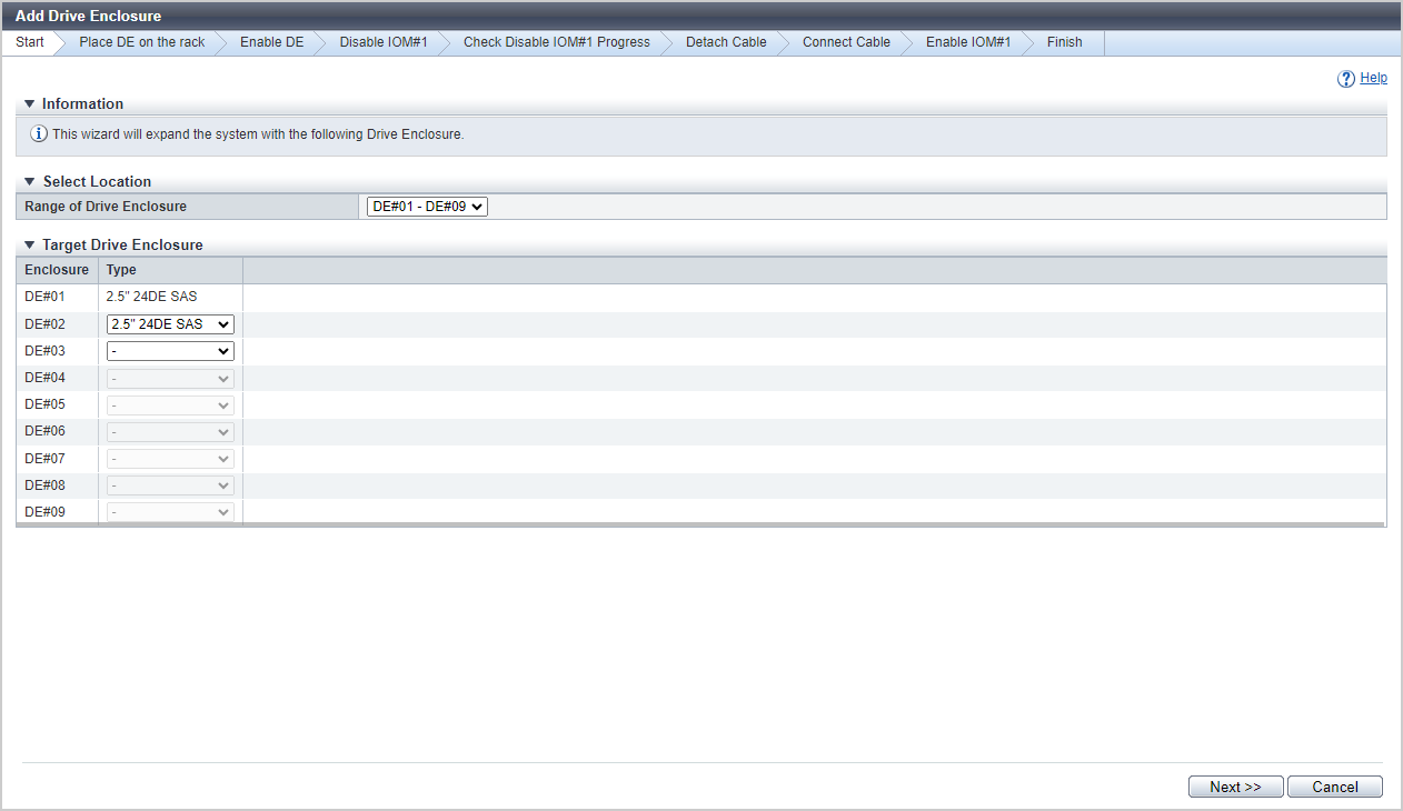
[Start] Screen
Select the DE that is to be added.
Select Location
| Item | Description |
|---|---|
Range of Drive Enclosure |
Select the range of the DEs that are to be added. In the list box, the range of the DEs that can be added at the one time is displayed. |
Target Drive Enclosure
| Item | Description |
|---|---|
|
Enclosure |
The DEs in the cascade that is selected with "Range of Drive Enclosure" are displayed. DE#n |
|
Type |
Select the DE type that is to be added. When the DE is not a target to be added, select "-" (hyphen). For the models that can add DEs, "2.5" 24DE" and "3.5" 12DE" can be selected. 2.5" 24DE NVMe 2.5" 24DE SAS 3.5" 12DE SAS |
[Place DE on the rack] Screen
Target Drive Enclosure
| Item | Description |
|---|---|
Enclosure |
The DE that is to be added is displayed. DE#n |
Type |
The DE type that is to be added is displayed. 2.5" 24DE NVMe 2.5" 24DE SAS 3.5" 12DE SAS |
Follow the procedure to connect the added DE with the following ports or DEs.
For the ETERNUS DX600 S6
DA Port No. |
Expandable DE | |||||||||
|---|---|---|---|---|---|---|---|---|---|---|
| 0 | - |
DE#01 | DE#02 | DE#03 | DE#04 | DE#05 | DE#06 | DE#07 | DE#08 | DE#09 |
| 1 | DE#10 | DE#11 | DE#12 | DE#13 | DE#14 | DE#15 | DE#16 | DE#17 | DE#18 | DE#19 |
| 2 | DE#20 | DE#21 | DE#22 | DE#23 | DE#24 | DE#25 | DE#26 | DE#27 | DE#28 | DE#29 |
| 3 | DE#30 | DE#31 | DE#32 | DE#33 | DE#34 | DE#35 | DE#36 | DE#37 | DE#38 | DE#39 |
For the ETERNUS DX900 S6
| CE No./ Port No. | Expandable DE | |||||||||||
|---|---|---|---|---|---|---|---|---|---|---|---|---|
| CE#0/Port#0 | - | DE#01 | DE#02 | DE#03 | DE#C0 | DE#C1 | DE#C2 | DE#C3 | DE#E0 | DE#E1 | DE#E2 | DE#E3 |
| CE#0/Port#1 | DE#04 | DE#05 | DE#06 | DE#07 | DE#C4 | DE#C5 | DE#C6 | DE#C7 | DE#E4 | DE#E5 | DE#E6 | DE#E7 |
| CE#0/Port#2 | DE#08 | DE#09 | DE#0A | DE#0B | DE#C8 | DE#C9 | DE#CA | DE#CB | DE#E8 | DE#E9 | DE#EA | DE#EB |
| CE#0/Port#3 | DE#0C | DE#0D | DE#0E | DE#0F | DE#CC | DE#CD | DE#CE | DE#CF | DE#EC | DE#ED | DE#EE | DE#EF |
| CE#1/Port#0 | - | DE#11 | DE#12 | DE#13 | DE#D0 | DE#D1 | DE#D2 | DE#D3 | DE#F0 | DE#F1 | DE#F2 | DE#F3 |
| CE#1/Port#1 | DE#14 | DE#15 | DE#16 | DE#17 | DE#D4 | DE#D5 | DE#D6 | DE#D7 | DE#F4 | DE#F5 | DE#F6 | DE#F7 |
| CE#1/Port#2 | DE#18 | DE#19 | DE#1A | DE#1B | DE#D8 | DE#D9 | DE#DA | DE#DB | DE#F8 | DE#F9 | DE#FA | DE#FB |
| CE#1/Port#3 | DE#1C | DE#1D | DE#1E | DE#1F | DE#DC | DE#DD | DE#DE | DE#DF | DE#FC | DE#FD | DE#FE | DE#FF |
For the ETERNUS DX8900 S6
| CE No./ Port No. | Expandable DE | |||
|---|---|---|---|---|
| CE#0/DA#0 Port#0 | - | DE#01 | DE#02 | DE#03 |
| CE#0/DA#0 Port#1 | DE#04 | DE#05 | DE#06 | DE#07 |
| CE#0/DA#1 Port#0 | DE#08 | DE#09 | DE#0A | DE#0B |
| CE#0/DA#1 Port#1 | DE#0C | DE#0D | DE#0E | DE#0F |
| CE#1/DA#0 Port#0 | - | DE#11 | DE#12 | DE#13 |
| CE#1/DA#0 Port#1 | DE#14 | DE#15 | DE#16 | DE#17 |
| CE#1/DA#1 Port#0 | DE#18 | DE#19 | DE#1A | DE#1B |
| CE#1/DA#1 Port#1 | DE#1C | DE#1D | DE#1E | DE#1F |
| CE#2/DA#0 Port#0 | - | DE#21 | DE#22 | DE#23 |
| CE#2/DA#0 Port#1 | DE#24 | DE#25 | DE#26 | DE#27 |
| CE#2/DA#1 Port#0 | DE#28 | DE#29 | DE#2A | DE#2B |
| CE#2/DA#1 Port#1 | DE#2C | DE#2D | DE#2E | DE#2F |
| CE#3/DA#0 Port#0 | - | DE#31 | DE#32 | DE#33 |
| CE#3/DA#0 Port#1 | DE#34 | DE#35 | DE#36 | DE#37 |
| CE#3/DA#1 Port#0 | DE#38 | DE#39 | DE#3A | DE#3B |
| CE#3/DA#1 Port#1 | DE#3C | DE#3D | DE#3E | DE#3F |
| CE#4/DA#0 Port#0 | - | DE#41 | DE#42 | DE#43 |
| CE#4/DA#0 Port#1 | DE#44 | DE#45 | DE#46 | DE#47 |
| CE#4/DA#1 Port#0 | DE#48 | DE#49 | DE#4A | DE#4B |
| CE#4/DA#1 Port#1 | DE#4C | DE#4D | DE#4E | DE#4F |
| CE#5/DA#0 Port#0 | - | DE#51 | DE#52 | DE#53 |
| CE#5/DA#0 Port#1 | DE#54 | DE#55 | DE#56 | DE#57 |
| CE#5/DA#1 Port#0 | DE#58 | DE#59 | DE#5A | DE#5B |
| CE#5/DA#1 Port#1 | DE#5C | DE#5D | DE#5E | DE#5F |
| CE#6/DA#0 Port#0 | - | DE#61 | DE#62 | DE#63 |
| CE#6/DA#0 Port#1 | DE#64 | DE#65 | DE#66 | DE#67 |
| CE#6/DA#1 Port#0 | DE#68 | DE#69 | DE#6A | DE#6B |
| CE#6/DA#1 Port#1 | DE#6C | DE#6D | DE#6E | DE#6F |
| CE#7/DA#0 Port#0 | - | DE#71 | DE#72 | DE#73 |
| CE#7/DA#0 Port#1 | DE#74 | DE#75 | DE#76 | DE#77 |
| CE#7/DA#1 Port#0 | DE#78 | DE#79 | DE#7A | DE#7B |
| CE#7/DA#1 Port#1 | DE#7C | DE#7D | DE#7E | DE#7F |
[Enable DE] Screen
Status Check
| Item | Description |
|---|---|
Enclosure |
The DE that is to be added is displayed. DE#n |
Type |
The DE type that is to be added is displayed. 2.5" 24DE NVMe 2.5" 24DE SAS 3.5" 12DE SAS |
Parts |
The components in the DE that is to be added are displayed. IOM#n PSU#n |
Progress |
The progress rate (0 to 100 %) of the activation process of the DE is displayed. |
Status |
The status of the DE that is to be added is displayed. |
[Disable IOM#1] Screen
Target Drive Enclosure
| Item | Description |
|---|---|
Enclosure |
The DE in which the parts that are to be disabled are installed is displayed. DE#n |
Type |
The type of the DE in which the components that are to be disabled are installed is displayed. 2.5" 24DE NVMe 2.5" 24DE SAS 3.5" 12DE SAS |
Parts |
The components that are to be disabled are displayed. IOM#1 |
Status |
The status of the components that are to be disabled is displayed. Refer to Component Status for details. |
[Check Disable IOM#1 Progress] Screen
Status Check
| Item | Description |
|---|---|
Enclosure |
The DE in which the component (IOM#1) that is to be isolated is installed is displayed. DE#n |
Type |
The type of the DE in which the component (IOM#1) that is to be isolated is installed is displayed. 2.5" 24DE NVMe 2.5" 24DE SAS 3.5" 12DE SAS |
Parts |
The components that are to be isolated are displayed. IOM#1 |
Progress |
The isolation progress rate (0 to 100 %) is displayed. |
Status |
The state of the part (IOM#1) that is to be isolated is displayed. |
[Finish] Screen
A message indicating that the DE was added successfully is displayed.
Operating Procedures
Click [Add Drive Enclosure] in [Action].
→ The [Start] Screen appears.
Specify the parameters, and click the [Next >>] button.
→ The [Place DE on the rack] Screen appears.
Add the DE according to the installation procedure and click the [Next >>] button.
→ The [Enable DE] Screen appears.
After the DEs are activated, isolate IOM#1.
→ The [Disable IOM#1] Screen appears.
Check the status of the target components and then click the [Next >>] button.
→ The [Check Disable IOM#1 Progress] Screen appears.
After IOM#1 is isolated, disconnect the backend cables.
Disconnect the backend cables by following the disconnection procedure and then click the [Next >>] button.
Connect the backend cables by following the connection procedure and then click the [Next >>] button.
→ The [Enable IOM#1] screen appears.
Enable the IOM#1 according to the installation procedure and click the [Next >>] button.
→ The [Finish] Screen appears.
Click the [Done] button to return to the [Drive Enclosure] screen.