


Hot Preventive Maintenance
Overview
This function replaces the components which may fail, while the storage system is operating.
Replacing maintenance parts can prevent malfunctions.
Availability of Hot Preventive Maintenance (for the ETERNUS DX600 S6) (Hot preventive maintenance is possible: , Hot preventive maintenance is not possible or not applicable: -)
| Component | Hot preventive maintenance | ||
|---|---|---|---|
| Controller Enclosure (CE) | - | ||
| Controller Module (CM) | |||
| Memory | (*1) | ||
| BUD | (*1) | ||
| FAN Unit | (*1) | ||
| PCIe SW | - | ||
| 64G FC-CA | |||
| SFP+ | |||
| 32G FC-CA | |||
| SFP+ | |||
| 16G FC-CA | |||
| SFP+ | |||
| 10G iSCSI-CA | |||
| SFP+ | |||
| SAS-DA | |||
| Backend Cable | |||
| NVMe-DA | |||
| Backend Cable | |||
| Controller Enclosure Power Supply Unit (CPSU) | |||
| Operation Panel (OPNL) | - | ||
| Battery Unit | - | ||
| Battery Control Unit (BCU) | |||
| Battery Unit (BTU) | |||
Drive |
|||
| Drive Enclosure (DE) | - | ||
Power Supply Unit (PSU) |
|||
| Drive | |||
| Panel | - | ||
| I/O Module (IOM) | |||
| Backend Cable (IN) | |||
| Backend Cable (OUT) | |||
| Power Cord | - | ||
| *1 | : | When the component is selected for hot preventive maintenance, the CM mounting the component is isolated. If the target component is "BUD", the CM is isolated. |
Availability of Hot Preventive Maintenance (for the ETERNUS DX8100 S6) (Hot preventive maintenance is possible: , Hot preventive maintenance is not possible or not applicable: -)
| Component | Hot Preventive Maintenance | ||
|---|---|---|---|
| Controller Enclosure (CE) | - | ||
| Controller Module (CM) | |||
| Memory | (*1) | ||
| BUD | (*1) | ||
| FAN Unit | (*1) | ||
| PCIe SW | - | ||
| 64G FC-CA | |||
| SFP+ | |||
| 32G FC-CA | |||
| SFP+ | |||
| 16G FC-CA | |||
| SFP+ | |||
| 10G iSCSI-CA | |||
| SFP+ | |||
| Controller Enclosure Power Supply Unit (CPSU) | |||
| Operation Panel (OPNL) | - | ||
| Battery Unit | - | ||
| Battery Control Unit (BCU) | |||
| Battery Unit (BTU) | |||
| Power Cord | - | ||
| Drive | (*2) | ||
| *1 | : | When the component is selected for hot preventive maintenance, the CM mounting the component is isolated. |
| *2 | : | A component that is installed in the CE of the ETERNUS DX8100 S6. |
Availability of Hot Preventive Maintenance (for the ETERNUS DX900 S6 or the ETERNUS DX8900 S6) (Hot preventive maintenance is possible: , Hot preventive maintenance is not possible or not applicable: -)
| Component | Hot Preventive Maintenance | ||
|---|---|---|---|
| Controller Enclosure (CE) | - | ||
| Controller Module (CM) | |||
| Memory | (*1) | ||
| BUD | |||
| FAN Unit | (*1) | ||
| PCIe SW | - | ||
| FRT Port | - | ||
| Management Cable | - | ||
| 64G FC-CA | |||
| SFP+ | |||
| 32G FC-CA | |||
| SFP+ | |||
| 16G FC-CA | |||
| SFP+ | |||
| 10G iSCSI-CA | |||
| SFP+ | |||
| SAS-DA | |||
| Backend Cable | |||
| NVMe-DA | |||
| Backend Cable | |||
| Controller Enclosure Power Supply Unit (CPSU) | |||
| Operation Panel (OPNL) | - | ||
| Battery Unit | - | ||
| Battery Control Unit (BCU) | |||
| Battery Unit (BTU) | |||
| Power Cord | - | ||
| Drive | |||
| Frontend Enclosure (FE) | - | ||
| Frontend Enclosure Power Supply Unit (FE PSU) | |||
| Frontend Router (FRT) | |||
| Frontend Cable | |||
| Service Controller (SVC) | |||
| Port | - | ||
| Management Cable | |||
| FE MP | - | ||
| FE MP BRG | - | ||
| Operation Panel (OPNL) | |||
| FAN Unit (FANU) | |||
| Drive Enclosure (DE) | - | ||
Power Supply Unit (PSU) |
|||
| Drive | |||
| Panel | - | ||
| I/O Module (IOM) | |||
| Backend Cable (IN) | |||
| Backend Cable (OUT) | |||
| Power Cord | - | ||
| *1 | : | When the component is selected for hot preventive maintenance, the CM mounting the component is isolated. |
Perform the start maintenance operation by using the [Start/End Maintenance] function before starting hot preventive maintenance. If the operation has not been performed, hot preventive maintenance cannot be started.
Hot preventive maintenance can be performed only on one component at a time.
This function can be performed when the component is in a normal state.
Be sure to use authorized maintenance parts for replacement. If components other than the authorized maintenance parts are used, operation is not guaranteed.
- Not all maintenance parts can be replaced by using this function. Refer to the following tables for the availability of hot preventive maintenance for each part.
- This function cannot be used under the following conditions:
The selected component is in the "Error" state
The selected component is not installed in the storage system (except drives)
The selected drive is being rebuilt
The Main CM is switched in the following conditions:
The Main CM is selected
The selected component is one of the following and the CM, on which the selected component is installed, is a Main CM
Memory
BUD
FAN Unit
Display Contents
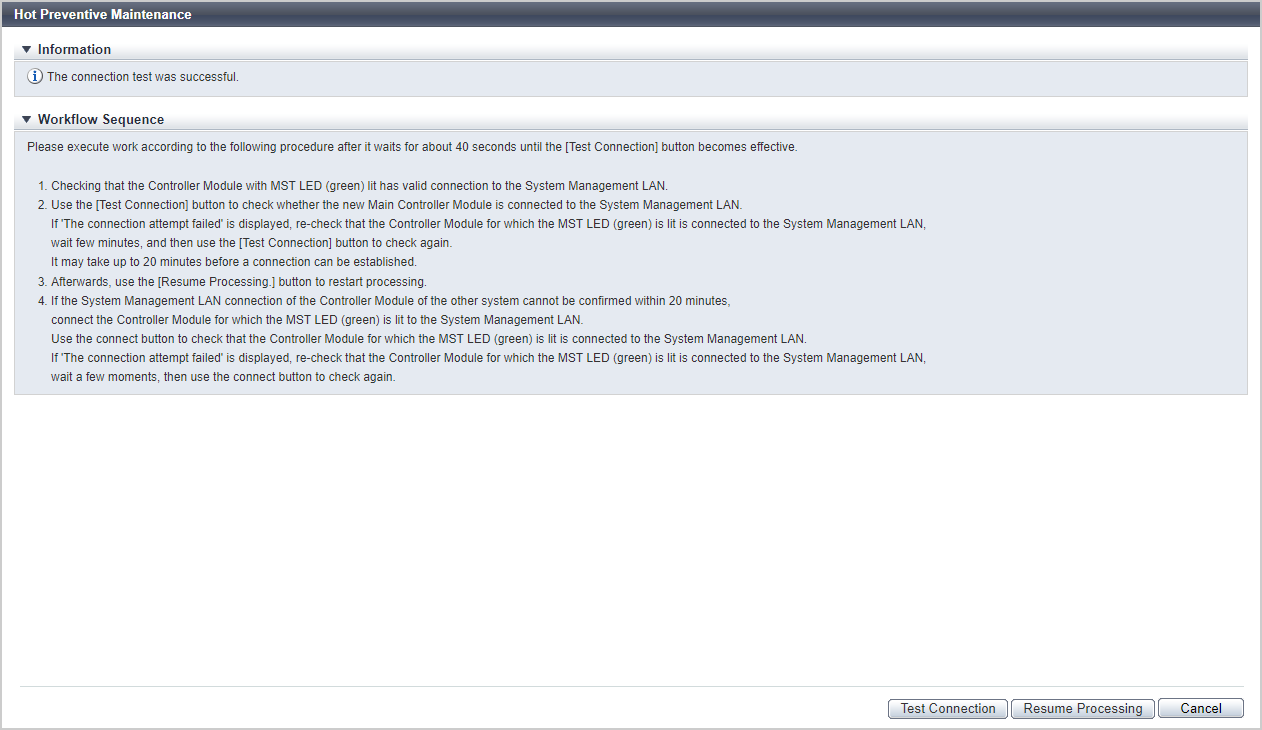
[Test Connection] Screen
This screen is displayed when the Main CM is affected by the hot preventive maintenance.
Follow the displayed procedure to confirm that the new Main CM is connected to a LAN.
Function Button
| Button | Description |
|---|---|
[Test Connection] |
Click this button after confirming that the new Main CM is connected to a LAN. The connection status of the new Main CM and the LAN is checked. |
[Test Connection Result] Screen
This screen is displayed when the Main CM is affected by the hot preventive maintenance.
The connection status check result of the new Main CM and the LAN is displayed.
Function Button
| Button | Description |
|---|---|
[Test Connection] |
If connection has failed, reconfirm the new Main CM is connected to a LAN, and click this button. The connection status of the new Main CM and the LAN is checked again. |
[Resume Processing] |
Click this button when connection was successful. Isolation of the CM starts. |
Operating Procedures
Select the component to perform preventive maintenance on, and click [Preventive Maintenance] in [Action].
→ A confirmation screen appears.
CautionWhen there is a component which can be affected by hot preventive maintenance, a message to that effect is displayed. Check the component which might be affected.
Click the [OK] button.
→ The operations to be started and the displayed screen vary depending on the conditions as follows.
When the Main CM can be affected by the hot preventive maintenance
→ The Main CM is switched, and the [Test Connection] Screen appears. Proceed to 3.
When the Main CM cannot be affected by the hot preventive maintenance
→ Isolation of the target component starts. Proceed to 6.
Follow the displayed procedure to confirm that the new Main CM is connected to a LAN.
After confirming the connection, click the [Test Connection] button.
→ The [Test Connection Result] Screen appears.
Confirm the connection status check result, and click the [Resume Processing] button.
→ Isolation of the target component starts.
CautionIf the connection of the new Main CM and the LAN fails, check the connection status again and return to 4.
Click the [Done] button to return to the screen when the target component was selected in 1.