


Remove Drive Enclosure
Overview
This function removes a Drive Enclosure (DE) without stopping the storage system.
After the target DEs are isolated, remove these DEs from the storage system.
Perform the start maintenance operation by using the [Start/End Maintenance] function before the removing task. If the operation has not been performed, the removal cannot be started.
When DE hot removal is performed, multiple DEs can be removed with a single operation.
Note that multiple DEs can only be removed when they are allocated to the same cascade configuration (*1). Multiple DEs that are allocated to different cascade configurations cannot be removed. Refer to DEs on the Same Cascade for details about the DEs that are on the same cascade.
*1 : "Cascade" refers to DEs that are connected to one Backend cable. The DEs that are sequentially located from the terminal DE in each cascade configuration can be removed.
2.5" DEs and 3.5" DEs can be removed at the same time.
- This function cannot be used under the following conditions:
-
Drives in the DE, which is to be removed, are registered in the RAID groups, the hot spares, the Thin Provisioning Pools, the Flexible Tier Pools, the REC Disk Buffers, or the Extreme Cache Pools.
- The status of the DE below is "Undefined"
For the ETERNUS DX600 S6: DE#01, DE#10, DE#20, and DE#30
For the ETERNUS DX900 S6: DE#x1, DE#x4, DE#x8, and DE#xC (x: 0 - 1)
For the ETERNUS DX8900 S6: DE#x1, DE#x4, DE#x8, and DE#xC (x: 0 - 7)
-
DEs on the Same Cascade
The DEs that are allocated to the same cascade configuration are as follows:
For the ETERNUS DX600 S6
DE#01, DE#02, DE#03, DE#04, DE#05, DE#06, DE#07, DE#08, DE#09, and DE#0A, which are connected to DA Port No.0.
DE#y0, DE#y1, DE#y2, DE#y3, DE#y4, DE#y5, DE#y6, DE#y7, DE#y8, DE#y9, and DE#yA, which are connected to DA Port No.x.
ETERNUS DX600 S6: x = 1 - 3, y = 1 - 3
(Example) DE#10, DE#11, DE#12, DE#13, DE#14, DE#15, DE#16, DE#17, DE#18, DE#19, and DE#1A, which are connected to DA Port No.1.
For the ETERNUS DX900 S6
Two CEs can be installed in the ETERNUS DX900 S6.
DE#x1, DE#x2, and DE#x3 that are connected to CE#x/DA Port#0 (x: 0 or 1)
DE#x4, DE#x5, DE#x6, and DE#x7 that are connected to CE#x/DA Port#1 (x: 0, 1, C, D, E, or F)
DE#x8, DE#x9, DE#xA, and DE#xB that are connected to CE#x/DA Port#2 (x: 0, 1, C, D, E, or F)
DE#xC, DE#xD, DE#xE, and DE#xF that are connected to CE#x/DA Port#3 (x: 0, 1, C, D, E, or F)
(Example) DE#01, DE#02, and DE#03 that are connected to CE#0/DA Port#0 are on the same cascade.
For the ETERNUS DX8900 S6
Multiple CEs can be installed in the ETERNUS DX8900 S6.
DE#x1, DE#x2, and DE#x3 that are connected to CE#x/DA#0 Port#0 (x:0 - 7)
DE#x4, DE#x5, DE#x6, and DE#x7 that are connected to CE#x/DA#0 Port#1 (x:0 - 7)
DE#x8, DE#x9, DE#xA, and DE#xB that are connected to CE#x/DA#1 Port#0 (x:0 - 7)
DE#xC, DE#xD, DE#xE, and DE#xF that are connected to CE#x/DA#1 Port#1 (x:0 - 7)
(Example) DE#01, DE#02, and DE#03 that are connected to CE#0/DA#0 Port#0 are on the same cascade.
Display Contents
The following screens are displayed by the wizard.
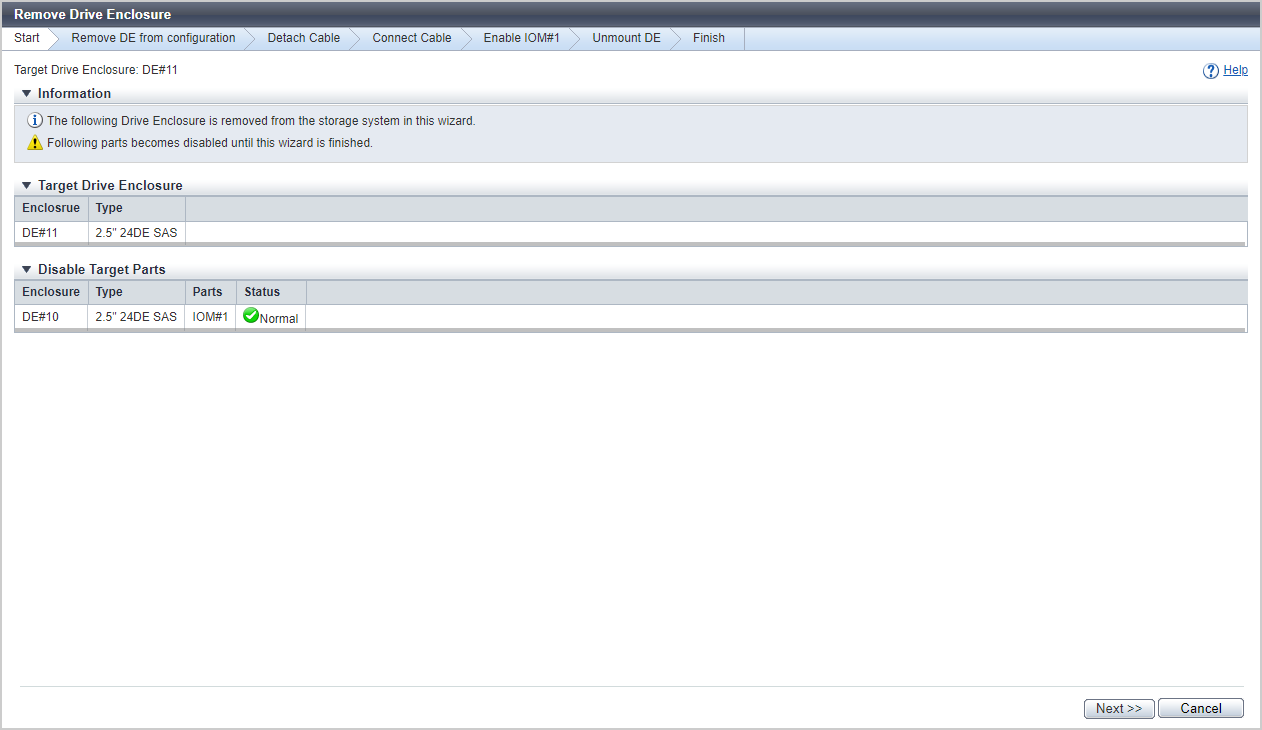
[Start] Screen
The DE that is to be removed is displayed.
Target Drive Enclosure
| Item | Description |
|---|---|
|
Enclosure |
The DE that is to be removed is displayed. DE#n |
|
Type |
The DE type that is to be removed is displayed. |
If DEs are removed while the storage system is running, a list of the components that will be disabled after the DEs are removed is displayed.
Disable Target Parts
| Item | Description |
|---|---|
|
Enclosure |
The DE in which the components that are to be disabled are installed is displayed. DE#n |
|
Type |
The type of the DE in which the components that are to be disabled are installed is displayed. |
|
Parts |
The components that are to be disabled are displayed. IOM#1 |
|
Status |
The status of the components that are to be disabled is displayed. Refer to Component Status for details. |
[Remove DE from configuration] Screen
The DEs that are to be removed are displayed as the target drive enclosures. When multiple DEs are removed, the items are separated with a "," (comma) and displayed.
The status of the components in the DE and the progress rate of isolating the DE are displayed in "Status Check".
Status Check
| Item | Description |
|---|---|
|
Enclosure |
The DEs in the target cascade configuration are displayed. DE#n |
|
Type |
The DE type is displayed. |
|
Parts |
The components in the DE that is to be removed are displayed. IOM#n PSU#n |
|
Progress |
The progress rate (0 to 100 %) of isolating the component is displayed. |
|
Status |
The component status is displayed. |
[Enable IOM#1] Screen
The DEs that are to be removed are displayed as the target drive enclosures. When multiple DEs are removed, the items are separated with a "," (comma) and displayed.
The activation progress of the IOM#1 with the backend cable is displayed in "Status Check".
Status Check
| Item | Description |
|---|---|
|
Enclosure |
The DEs that remain in the target cascade configuration are displayed. DE#n |
|
Type |
The DE type is displayed. |
|
Parts |
The components in the DE that is to be removed are displayed. IOM#n |
|
Progress |
The component activation progress rate (0 to 100 %) is displayed. |
|
Status |
The component status is displayed. |
[Unmount DE] Screen
The DE removal procedure is displayed on this screen. Remove the DE according to the displayed procedure.
| Item | Description |
|---|---|
|
Target Drive Enclosure |
The DE that is to be removed is displayed. DE#n |
|
Type |
The DE type is displayed. |
[Finish] Screen
A message that indicates the DE is removed successfully is displayed.
Operating Procedures
Select DEs that are to be removed (multiple selections can be made), and click [Remove Drive Enclosure] in [Action].
→ The [Start] Screen appears.
Check the DE to be removed, and click the [Next >>] button.
→ The DEs in the same cascade configuration as the target DEs are isolated. The [Remove DE from configuration] Screen appears.
When the DE isolation is complete, the [Detach Cable] screen appears.
Disconnect the backend cables by following the displayed procedure and then click the [Next >>] button.
The screen that is displayed depends on the DE status in the target cascade configuration.
When there are DEs that remain in the cascade configuration after the target DEs are removed
→The [Connect Cable] screen appears. Proceed to 4.
When all of the removal processes for the relevant DEs are complete
→ The [Unmount DE] Screen appears. Proceed to 5.
Connect the backend cables according to the displayed procedure and click the [Next >>] button.
→ The activation of IOM#1, which was not removed, starts. The [Enable IOM#1] Screen is displayed.
After IOM#1 is activated, the [Unmount DE] Screen appears.
Remove the relevant DE from the storage system according to the displayed workflow and click the [Next >>] button.
→ The [Finish] Screen appears.
Click the [Done] button to return to the [Drive Enclosure] screen.