


I/O Modules
The I/O module is a component that controls how the controller and the drives interact.
The I/O module is connected to the DA port of the controller or an I/O module on another drive enclosure. A drive enclosure has two I/O modules.
I/O modules have ports and LEDs.
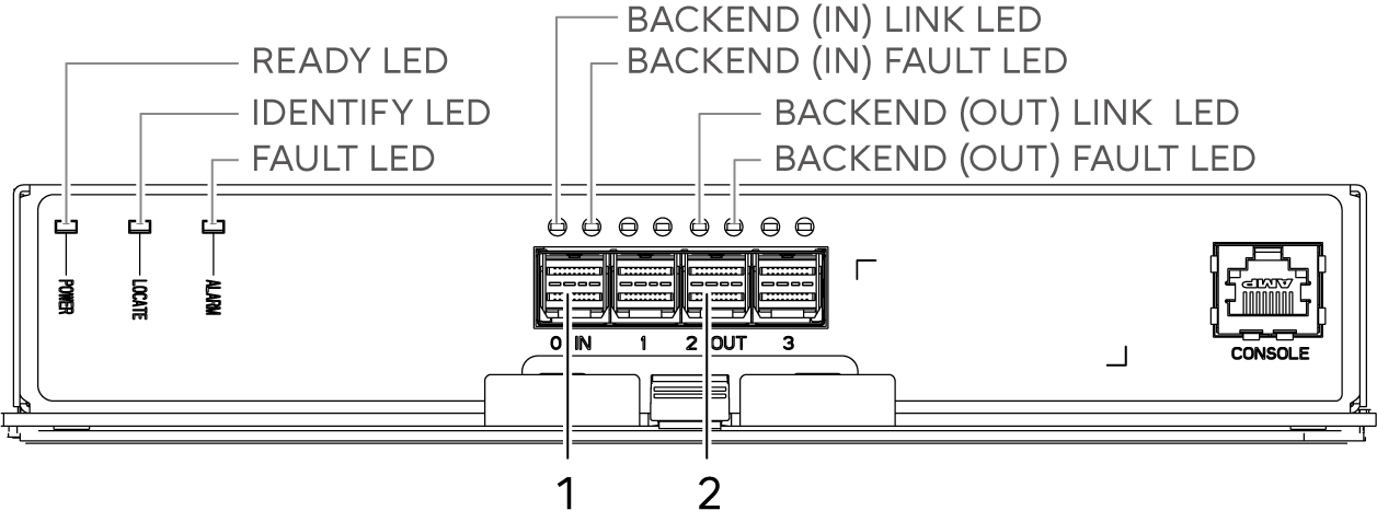
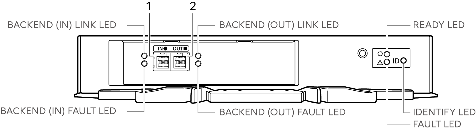
Backend (IN) port
This port is used to connect between enclosures.
Backend (OUT) port
This port is used to connect between enclosures.
The LEDs turn on or blink to indicate the statuses that are listed below.
LED name |
LED status |
Meaning |
|---|---|---|
BACKEND (IN) LINK |
|
The link between the backend (IN) port and the source port has been established. |
BACKEND (IN) FAULT |
|
|
|
The ports to connect the cables are indicated. This occurs while a drive enclosure is being added. |
|
BACKEND (OUT) LINK |
|
The link between the backend (OUT) port and the destination port has been established. |
BACKEND (OUT) FAULT |
|
The link between the backend (OUT) port and the destination port is in error status. |
|
The ports to connect the cables are indicated. This occurs while a drive enclosure is being added. |
|
READY |
|
The I/O module is in normal status. |
IDENTIFY |
|
The installation location of the I/O module is identified according to the instruction that is issued from ETERNUS Web GUI or ETERNUS CLI. |
FAULT |
|
The I/O module is in error status. |