


Add Controller Enclosure
Overview
This function adds a Controller Enclosure (CE) without stopping the storage system.
After installing a CE for the storage system, activate it via Web GUI.
The number of CEs that can be added is as follows:
For the ETERNUS DX900 S5: CE#1
For the ETERNUS DX8900 S4: CE#1 - CE#B
CEs must be added one at a time.
Perform the start maintenance operation by using the [Start/End Maintenance] function before adding a CE. If the operation has not been performed, addition cannot be started.
Be sure to use authorized additional parts. If parts other than the additional parts are used, operation is not guaranteed.
The Controlling CM for the existing RAID groups is not changed just by adding CEs. (RAID groups are not assigned to the added CMs.) After adding CEs, reassign the Controlling CM for the RAID groups using all CMs including the added CMs. Refer to the [Change Controlling CM] function for details.
Do not add CEs when Storage Migration paths are set.
- This function cannot be used under the following conditions:
Multiple CEs that are targets of a cold addition have been installed
The general status of the storage system is not "Normal" (except when using this function to recover the CE adding process (*1))
*1 : When adding the target CE again after the adding process failed midway through, this function must be started over from the beginning. The "recovery" process initializes (or restores) the CE to the state prior to installing in the storage system. There are no CEs that can be the target of a hot addition, cold addition, or recovery
- One of the following functions is being performed in the storage system:
Format volume
Expand volume (LUN Concatenation)
Encrypt volume
Format TPP
Format FTRP
Expand RAID group (LDE)
There is an REC session in a status other than "Suspend"
There is a RAID group in the "Rebuild", "Copyback", or "Redundant Copy" state
To add a CE in cold mode, turn off the storage system, install the target CE, and connect the cables between the CE and the FE. After turning on the storage system, activate the CE via Web GUI.
If the storage system is configured with four CEs and "ETERNUS DX8900 S4 (4controller enclosure or less)" is being used, CEs cannot be added. Replace "Expansion Frontend enclosure for DX8900 S4" in advance and start this function again.
| The Procedure for Adding a Controller Enclosure in Hot Mode |
|---|
|
User Privileges
Availability of Executions in the Default Role
| Default role | Availability of executions |
|---|---|
| Monitor | |
| Admin | |
| StorageAdmin | |
| AccountAdmin | |
| SecurityAdmin | |
| Maintainer |
Refer to "User Roles and Policies" for details on the policies and roles.
Display Contents
The following screens are displayed by the wizard.
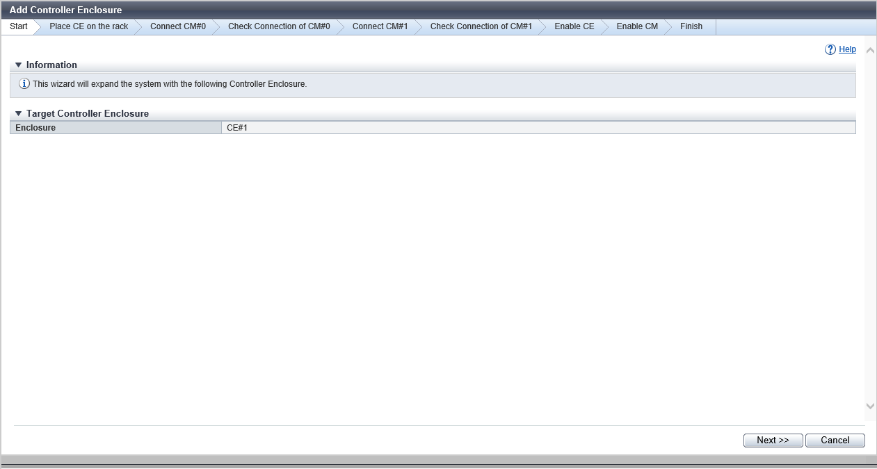
[Start] Screen
The CE that is to be added is displayed.
Target Controller Enclosure
| Item | Description |
|---|---|
|
Enclosure |
The CE number that is to be added is displayed. CE#x x: CE number |
[Start] Screen (Initialization Progress)
The status monitoring progress for the CE and CM that are to be added is displayed.
This screen is displayed when adding the target CE in cold mode or when recovering the CE adding process.
Status Check
| Item | Description |
|---|---|
|
Parts |
The status monitoring target component is displayed. CE#x CE#x CM#y x: CE number y: CM number |
|
Progress |
The progress rate (0 to 100 %) of the status monitoring is displayed. |
|
Status |
The status of the monitoring target components is displayed. |
[Start] Screen (Detach Cable)
The cable and CE removal procedures are displayed.
This screen is displayed when recovering the CE adding process.
[Place CE on the rack] Screen
The procedure to install a CE is displayed.
[Connect CM#0] Screen
The cable connection procedure for CM#0 is displayed.
[Check Connection of CM#0] Screen
The cable connection progress for CM#0 is displayed with a bar and progress rate.
Status Check
| Item | Description |
|---|---|
|
Parts |
The port that is connected to the target CM is displayed. FRT#x Port (CE#y CM#0) SVC#z Port (CE#y CM#0) x: FRT number y: CE number z: SVC number |
|
Progress |
The status monitoring progress rate (0 to 100 %) of the target component is displayed. |
|
Status |
The port status that is connected to the target CM is displayed. |
[Connect CM#1] Screen
The cable connection procedure for CM#1 is displayed.
[Check Connection of CM#1] Screen
The cable connection progress for CM#1 is displayed with a bar and progress rate.
Status Check
| Item | Description |
|---|---|
|
Parts |
The port that is connected to the target CM is displayed. FRT#x Port (CE#y CM#1) SVC#z Port (CE#y CM#1) x: FRT number y: CE number z: SVC number |
|
Progress |
The status monitoring progress rate (0 to 100 %) of the target component is displayed. |
|
Status |
The port status that is connected to the target CM is displayed. |
[Enable CE] Screen
The progress rate of the activation process of the CE is displayed.
Status Check
| Item | Description |
|---|---|
|
Parts |
The components in the CE that is to be added are displayed. CE#x CM#y CE#x CM#y DMA Port#z FRT#w Port (CE#x CM#y) SVC#v Port (CE#x CM#y) CE#x CPSU#X CE#x BCU#Y CE#x BTU#Z x: CE number y: CM number z: DMA Port number w: FRT number v: SVC number X: CPSU number Y: BCU number Z: BTU number |
|
Progress |
The component activation progress rate (0 to 100 %) is displayed. |
|
Status |
The component status in the CE that is to be added is displayed. |
[Enable CM] Screen
The progress rate of the activation process of the CM is displayed.
Status Check
| Item | Description |
|---|---|
|
Parts |
The CMs in the CE that is to be added are displayed. CE#x CM#y x: CE number y: CM number |
|
Progress |
The progress rate (0 to 100 %) of the activation process of the CM is displayed. |
|
Status |
The CM status in the CE that is to be added is displayed. |
[Finish] Screen
A message indicating that the CE was added successfully is displayed.
Operating Procedures
Click [Add Controller Enclosure] in [Action].
→ The [Start] Screen appears.
Click the [Next >>] button.
→ The displayed screen may vary depending on whether the recovery CE adding process is required or not.
When the recovery CE adding process is required:
→ The [Start] Screen (Initialization Progress) appears. When the initialization is complete, the [Start] Screen (Detach Cable) appears. Proceed to Step 3.
When the recovery CE adding process is not required
→ The [Place CE on the rack] Screen appears. Proceed to Step 4.
Disconnect the cables and the CE according to the displayed procedure and click the [Next >>] button.
→ The [Place CE on the rack] Screen appears.
Mount the CE in the rack according to the displayed procedure and click the [Next >>] button.
→ The [Connect CM#0] Screen appears.
Connect the cables according to the displayed procedure and click the [Next >>] button.
→ The [Check Connection of CM#0] Screen appears. After connecting cables is complete, the [Connect CM#1] Screen appears.
Connect the cables according to the displayed procedure and click the [Next >>] button.
→ The [Check Connection of CM#1] Screen appears. After connecting cables is complete, the [Enable CE] Screen appears.
Check the activation state of the CE.
→ After the CE activation is complete, the [Enable CM] Screen appears.
Check the activation state of the CM.
→ When the CM activation is complete, the [Finish] Screen appears.
Click the [Done] button to return to the [Controller Enclosure] screen.
NoteThe Controlling CM for the existing RAID groups is not changed just by adding CEs. After adding CEs, reassign the Controlling CM for the RAID groups using all CMs including the added CMs. Refer to the [Change Controlling CM] function for details.