


Setup Network Environment
Overview
This function sets up an the environment for the storage system to communicate with an external network.
Configuration is required for each MNT, RMT and FST port.
MNT port
The MNT port is used for general communication between the storage system and the external hosts.
For the ETERNUS DX60 S5/DX100 S5/DX200 S5 and the ETERNUS AF150 S3/AF250 S3, this port is also used for maintenance of the storage system.
RMT port
The RMT port is used when the line must be separated from the MNT port.
This port must be configured for the ETERNUS DX500 S5/DX600 S5/DX900 S5, the ETERNUS DX8100 S4/DX8900 S4, and the ETERNUS AF650 S3.
FST port
The FST port is used for maintenance of the storage system.
This port must be configured for the ETERNUS DX500 S5/DX600 S5/DX900 S5, the ETERNUS DX8100 S4/DX8900 S4, and the ETERNUS AF650 S3.
If the message "Currently Network Configuration is set to factory default." is displayed in the system message field, the network environment settings must be performed. Some functions are not available if the network environment settings for the MNT port are incomplete. Refer to "Functions that cannot be performed in a factory default network environment" for details.
Logging in again may be required after the settings are complete.
MNT ports and RMT ports support both "IPv4" and "IPv6". FST ports only support "IPv4".
Both or either "IPv4 address" and "IPv6 address" can be set for a port.
When the network environment settings are the same as the factory default, all the input items in the [IPv4 Settings] tab for the MNT port are cleared. Information that is configured in the storage system is not displayed. Note that in the [IPv6 Settings] tab, the information that is configured in the storage system is displayed.
When SNMP Manager exists in a different subnetwork from the storage system, specify the IP address or the network address of SNMP Manager in "Allowable IP Address" of this function.
Available operations vary depending on the models and ports. Refer to "Available Port Operations for each Model" for details.
To enable or disable each service (such as HTTP and HTTPS), use the [Setup Firewall] function.
|
|---|
|
|
||||||||||||||||||||||||||||||||||||||||||||||||||||||||||||||||||||||||
|---|---|---|---|---|---|---|---|---|---|---|---|---|---|---|---|---|---|---|---|---|---|---|---|---|---|---|---|---|---|---|---|---|---|---|---|---|---|---|---|---|---|---|---|---|---|---|---|---|---|---|---|---|---|---|---|---|---|---|---|---|---|---|---|---|---|---|---|---|---|---|---|---|
|
||||||||||||||||||||||||||||||||||||||||||||||||||||||||||||||||||||||||
User Privileges
Availability of Executions in the Default Role
| Default role | Availability of executions |
|---|---|
| Monitor | |
| Admin | |
| StorageAdmin | |
| AccountAdmin | |
| SecurityAdmin | |
| Maintainer |
Refer to "User Roles and Policies" for details on the policies and roles.
Display Contents
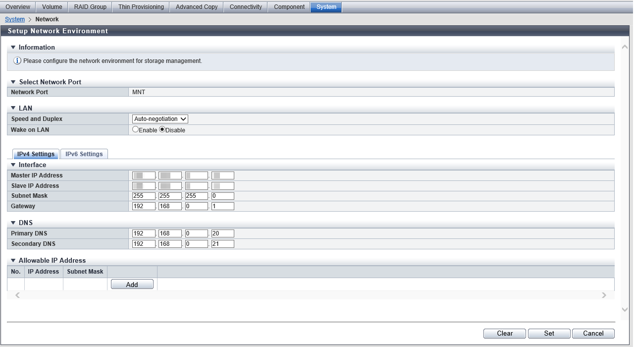
Select Network Port
| Item | Description |
|---|---|
Network Port |
The port that is to be set is displayed. For the ETERNUS DX60 S5/DX100 S5/DX200 S5 and ETERNUS AF150 S3/AF250 S3 MNT RMT For the other models MNT RMT FST |
Settings
LAN
| Item | Description | Setting values | |||
|---|---|---|---|---|---|
Speed and Duplex |
Select the communication speed and mode. |
Auto-negotiation (Default) 1Gbit/s 100Mbit/s Half 100Mbit/s Full 10Mbit/s Half 10Mbit/s Full |
|||
Wake on LAN |
Select whether to enable or disable the WOL function (*1). This item is not displayed when an FST port is selected.
|
Enable Disable (Default) |
MNT ports or RMT ports support "IPv4" and "IPv6". Click the [IPv4 Settings] Tab or [IPv6 Settings] Tab to set the network environment. FST ports only support "IPv4". Specify "Interface" in the [IPv4 Settings] Tab.
[IPv4 Settings] Tab
In this screen, configure the network environment for IPv4.
Interface
| Item | Description | Setting values |
|---|---|---|
Master IP Address |
Input the IP address for the Master CM of the storage system. |
Numeric characters for all the text boxes (0 - 255) For the ETERNUS DX60 S5/DX100 S5/DX200 S5 and ETERNUS AF150 S3/AF250 S3
For the other models
|
Slave IP Address |
Input the IP address for the Slave CM of the storage system. The IP address of the Slave CM is used when an error occurs in the Master CM. This item is not displayed for the 1CM model. |
Numeric characters for all the text boxes (0 - 255) |
Subnet Mask |
Input the subnet mask of the storage system. |
255.0.0.0 - 255.255.255.252 For the ETERNUS DX60 S5/DX100 S5/DX200 S5 and ETERNUS AF150 S3/AF250 S3
For the other models
|
Gateway |
Input the IP address of the gateway. This item is not displayed when an FST port is selected. |
Numeric characters for all the text boxes (0 - 255) |
DNS
This item is not displayed when an FST port is selected.
| Item | Description | Setting values |
|---|---|---|
Primary DNS |
Input the IP address of the Primary DNS server. |
Numeric characters for all the text boxes (0 - 255) |
Secondary DNS |
Input the IP address of the Secondary DNS server. The Secondary DNS server must be specified after the Primary DNS server. |
Numeric characters for all the text boxes (0 - 255) |
Allowable IP Address
This item can be configured when the gateway is specified. This item is not displayed when an FST port is selected.
Up to 16 addresses are displayed.
| Item | Description |
|---|---|
No. |
The number (#1 to #16) of the allowable IP address (or network address) is displayed. |
IP Address |
The allowable IP address (or network address) is displayed. |
Subnet Mask |
The subnet mask for the allowable IP address (or network address) is displayed. |
Function Button
| Button | Description |
|---|---|
[Add] |
Adds an IP address (or the network address) of the remote storage system to "Allowable IP Address". If the maximum number of addresses has already been registered, the [Add] button cannot be clicked. |
[Delete] |
Deletes an IP address (or the network address) of the remote storage system from "Allowable IP Address". When no IP address (or network address) of the remote storage system is not added in the list, the [Delete] button is not displayed. |
[Add Allowable IP Address] Screen
In this screen, input the information of the remote storage systems for which network access will be allowed.
Allowable IP Address Settings
| Item | Description | Setting values |
|---|---|---|
IP Address |
Input the IP address (or the network address) for the remote storage system. Make sure to input the IP address (or the network address) and subnet mask in pairs. |
Numeric characters for all the text boxes (0 - 255) |
Subnet Mask |
Input the subnet mask for the IP address (or the network address) of the remote storage system. |
255.0.0.0 - 255.255.255.252 |
[IPv6 Settings] Tab
In this screen, configure the network environment for IPv6.
Click the [Automatic discovery] button to obtain setting information in the "Interface" field.
Interface
| Item | Description | Setting values |
|---|---|---|
Master IP Link Local Address |
Input the link local address (interface ID) for the Master CM of the storage system. Note that the link local address is only available within the same network and cannot be connected to the Internet. Connection via a router is not available. Refer to "Available IPv6 Address" for details. When the current setting is displayed, the IPv6 address is displayed as an abbreviation. |
fe80::xxxx:xxxx:xxxx:xxxx xxxx: 0 - ffff (FFFF) (hexadecimal, alphanumeric characters) Refer to "IPv6 Address Notation" for details. The link local address that is based on the storage system WWN (Default) |
Master Connect IP Address |
Input the connect IP address for the Master CM of the storage system. "Master Connect IP Address" corresponds to "Master IP Address" for IPv4. "Global address", "unique local address", or "6to4 address" can be input for the IPv6 address. Refer to "Available IPv6 Address" for details. When the current setting is displayed, the IPv6 address is displayed as an abbreviation. |
xxxx:xxxx:xxxx:xxxx:xxxx:xxxx:xxxx:xxxx xxxx: 0 - ffff (FFFF) (hexadecimal, alphanumeric characters) Refer to "IPv6 Address Notation" for details. |
Slave IP Link Local Address |
Input the link local address (interface ID) for the Slave CM of the storage system. The link local address of the Slave CM is used when an error occurs in the Master CM. Refer to "Available IPv6 Address" for details. When the current setting is displayed, the IPv6 address is displayed as an abbreviation. This item is not displayed for the 1CM model. |
fe80::xxxx:xxxx:xxxx:xxxx xxxx: 0 - ffff (FFFF) (hexadecimal, alphanumeric characters) Refer to "IPv6 Address Notation" for details. |
Slave Connect IP Address |
Input the connect IP address for the Slave CM of the storage system. The connect IP address of the Slave CM is used when an error occurs in the Master CM. "Slave Connect IP Address" corresponds to "Slave IP Address" for IPv4. "Global address", "unique local address", or "6to4 address" can be input for the IPv6 address. Refer to "Available IPv6 Address" for details. When the current setting is displayed, the IPv6 address is displayed as an abbreviation. This item is not displayed for the 1CM model. |
xxxx:xxxx:xxxx:xxxx:xxxx:xxxx:xxxx:xxxx xxxx: 0 - ffff (FFFF) (hexadecimal, alphanumeric characters) Refer to "IPv6 Address Notation" for details. |
Length of Subnet Prefix |
Input the prefix length of the connect IP address (unit: bit). "Length of Subnet Prefix" corresponds to "Subnet Mask" for IPv4. |
3 - 128 Refer to "Available IPv6 Address" for details. |
Gateway |
Input the IP address of the gateway. The following IPv6 addresses can be used; "link local address", "global address", "unique local address", or "6to4 address". Refer to "Available IPv6 Address" for details. When the current setting is displayed, the IPv6 address is displayed as an abbreviation. |
xxxx:xxxx:xxxx:xxxx:xxxx:xxxx:xxxx:xxxx xxxx: 0 - ffff (FFFF) (hexadecimal, alphanumeric characters) Refer to "IPv6 Address Notation" for details. |
DNS
| Item | Description | Setting values |
|---|---|---|
Primary DNS |
Input the IP address of the Primary DNS server. "Global address", "unique local address", or "6to4 address" can be input for the IPv6 address. Refer to "Available IPv6 Address" for details. When the current setting is displayed, the IPv6 address is displayed as an abbreviation. |
xxxx:xxxx:xxxx:xxxx:xxxx:xxxx:xxxx:xxxx xxxx: 0 - ffff (FFFF) (hexadecimal, alphanumeric characters) Refer to "IPv6 Address Notation" for details. |
Secondary DNS |
Input the IP address of the Secondary DNS server. The Secondary DNS server must be specified after the Primary DNS server. "Global address", "unique local address", or "6to4 address" can be input for the IPv6 address. Refer to "Available IPv6 Address" for details. When the current setting is displayed, the IPv6 address is displayed as an abbreviation. |
xxxx:xxxx:xxxx:xxxx:xxxx:xxxx:xxxx:xxxx xxxx: 0 - ffff (FFFF) (hexadecimal, alphanumeric characters) Refer to "IPv6 Address Notation" for details. |
Allowable IP Address
This item can be configured when the gateway is specified.
Up to 16 addresses are displayed.
| Item | Description |
|---|---|
No. |
Number (#1 to #16) for the connect IP address of the remote storage system is displayed. |
Connect IP Address |
The connect IP address of the remote storage system is displayed. Note that the current setting is displayed by an abbreviation. Refer to "IPv6 Address Notation" for details. |
Length of Subnet Prefix |
The prefix length for the connect IP address of the remote storage system (3 to 128) is displayed (unit: bit). |
Function Button
| Button | Description |
|---|---|
[Automatic discovery] |
Click this button to obtain the following information:
For the "Link Local Address" field, a unique IP address within the same network that is created from the storage system information is specified. For the "Connect IP Address" field, an IP address is created by combining the prefix information that is automatically obtained from the router with the unique identifier (interface ID) of the link local address. |
[Add] |
Adds the connection IP address for the remote storage system to "Allowable IP Address". If the maximum number of addresses has already been registered, the [Add] button cannot be clicked. |
[Delete] |
Deletes a connection IP address of the remote storage system from "Allowable IP Address". When a connect IP address of the remote storage system is not added in the list, the [Delete] button is not displayed. |
[Add Allowable IP Address] Screen
In this screen, input the information of the remote storage systems for which network access will be allowed.
Allowable IP Address Settings
| Item | Description | Setting values |
|---|---|---|
Connect IP Address |
Input the connect IP address that is to be displayed. "Global address", "unique local address", or "6to4 address" can be input for the IP address. Refer to "Available IPv6 Address" for details. Make sure to input "Connect IP Address" and "Length of Subnet Prefix" together. |
xxxx:xxxx:xxxx:xxxx:xxxx:xxxx:xxxx:xxxx xxxx: 0 - ffff (FFFF) (hexadecimal, alphanumeric characters) Refer to "IPv6 Address Notation" for details. |
Length of Subnet Prefix |
Input the prefix length of the connect IP address for the remote storage system (unit: bit). |
3 - 128 Refer to "Available IPv6 Address" for details. |
IPv6 Address Notation
Since the IPv6 address is 128-bit and extremely long, this address is displayed using "xxxx", which describes 16-bit in hexadecimals as being one block that is separated by colons (":").
xxxx:xxxx:xxxx:xxxx:xxxx:xxxx:xxxx:xxxx
• Use 0 - ffff (FFFF) (hexadecimal, alphanumeric characters) for inputting an IPv6 address
• The current setting is displayed with 0 - ffff (hexadecimal, "a" - "f" are lowercase letters)
• Up to 128-bit
• The first 64-bit (prefix) of the link local address is fixed to "fe80::"
The following three abbreviation methods are available for IPv6 addresses:
(1) Omission of the first "0" of a block that follows consecutive zeros.
[Example] 2001:1000:0120:0000:0000:0123:0000:0000
↓
2001:1000:120:0000:0000:123:0000:0000
(2) Replacement of "0000" blocks with "0".
[Example] 2001:1000:120:0000:0000:123:0000:0000
↓
2001:1000:120:0:0:123:0:0
(3) Replacement of a block with consecutive zeros by "::" is performed only once.
[Example] 2001:1000:120:0:0:123:0:0
↓
2001:1000:120::123:0:0 is OK
2001:1000:120::123:: is not allowed (Replacement of a block with consecutive zeros by "::" is allowed only once.)
- The following IP addresses cannot be specified:
Link local addresses for which all of the values for the low 64-bit are "0"
Connect IP addresses (*1) for which the first 3-bit are not "001" or the first 7-bit are not "1111110"
*1 : The connect IP address indicates either a "global address", "unique local address", or "6to4 address". The first 64-bit of the gateway is "fe80::" and all of the values for low 64-bit are "0"
Network addresses for which the first 3-bit of the gateway are "001"
Network addresses for which the first 7-bit of the gateway are "1111110"
DNS server IP addresses for which the first 3-bit are not "001" or the first 7-bit are not "1111110"
Available IPv6 Address
| No. | Allocated addresses | Settable range for addresses | Length of subnet prefix |
|---|---|---|---|
| 1 | Global address | 2000::1 - 3fff:ffff:ffff:ffff:ffff:ffff:ffff:ffff | 3 - 128 |
| 2 | Unique local address | fc00::1 - fdff:ffff:ffff:ffff:ffff:ffff:ffff:ffff | 7 - 128 |
| 3 | Link local address | fe80::1 - fe80::ffff:ffff:ffff:ffff | 64-bit static IP address |
| 4 | 6to4 address | 2002:<IPv4 address in hexadecimal>::1 - 2002:<IPv4 address in hexadecimal>::ffff:ffff:ffff:ffff | 48 - 128 |
Supplementary Information
When accessing of the storage system from a different subnetwork is not allowed
Specify "IP Address" and "Subnet Mask" of the storage system.
Only accessing from the same subnetwork is allowed.
When accessing of the storage system from a different subnetwork is allowed
Specify "Gateway" and "Allowable IP Address ("IP Address" (or "Network Address") and "Subnet Mask")".
[Example] Allowable IP Address (for IPv4)
When accessing of the storage system from a specific client outside the subnetwork is allowed, specify "IP Address" and "Subnet Mask".
IP Address: 10.20.30.40
Subnet Mask: 255.255.255.255
When accessing of the storage system from a specific subnetwork outside the subnetwork is allowed, specify "Network Address" and "Subnet Mask".
IP Address: 10.20.30.0
Subnet Mask: 255.255.255.0
Operating Procedures
In this screen, configure the network environment for each port.
When Using IPv4
Select which port that the network environment is to be set for, and click [Setup Network Environment] in [Action].
Specify the parameters.
To allow access from a different subnetwork to the storage system, click the [Add] button.
→ The [Add Allowable IP Address] Screen appears.
Input the IP address and the subnet mask, and then click the [OK] button.
→ Returns to the [Setup Network Environment] screen.
Repeat Step 3 and Step 4 when registering multiple allowable IP addresses.
After registering the allowable IP address is complete, click the [Set] button.
→ A confirmation screen appears.
Caution- When specifying the IP address or the subnet mask, note the following:
IP addresses must be specified with the IPv4 format.
The IP address of the RMT port must be in a different subnetwork from the MNT port.
Specify the IP address of the Slave CM when connecting to the Slave CM. The IP address of the Slave CM must be in the same subnetwork as the Master CM.
Specify the IP address of "Gateway" when allowing access from outside of the subnetwork. The IP address must be in the same subnetwork as the port.
For "Allowable IP Address", specify the IP address or the network address that is allowed to access to the storage system. These settings are not required for access from the network address (same subnetwork) which the storage system belongs to.
For "DNS", specify different IP addresses for the MNT port and RMT port.
Click the [Clear] button to delete setting parameters. Note that the parameters cannot be deleted if no other ports are available.
- When specifying the IP address or the subnet mask, note the following:
Click the [OK] button.
→ The network environment settings starts.
Click the [Done] button to return to the [Network] screen.
CautionStorage system management operation cannot be continued if the IP address of the storage system has been changed. Logging in again with the new IP address is required.
When Using IPv6
Select which port that the network environment is to be set for, and click [Setup Network Environment] in [Action].
Specify the parameters.
NoteClick the [Automatic discovery] button to automatically obtain "Master IP Link Local Address", "Master Connect IP Address", "Slave IP Link Local Address", "Slave Connect IP Address", "Length of Subnet Prefix", and "Gateway". Input the IPv6 address of the DNS server if required.
To allow access from a different subnetwork to the storage system, click the [Add] button.
→ The [Add Allowable IP Address] Screen appears.
Input "Connect IP Address" and "Length of Subnet Prefix", and click the [OK] button.
→ Returns to the [Setup Network Environment] screen.
Repeat Step 3 and Step 4 when registering multiple allowable IP addresses.
After registering the allowable IP address is complete, click the [Set] button.
→ A confirmation screen appears.
Caution- Note the following points when specifying an IP address:
IP addresses must be specified with the IPv6 format. Refer to "IPv6 Address Notation" for details.
The connect IP address of the RMT port must be in a different subnetwork from the MNT port.
Specify the connect IP address of the Slave CM when connecting to the Slave CM. The IP address of the Slave CM must be in the same subnetwork as the Master CM.
Specify the IP address of "Gateway" when allowing access from outside of the subnetwork. The IP address must be in the same subnetwork as the port.
For "Allowable IP Address", specify the IP address or the network address that is allowed to access to the storage system. These settings are not required for access from the network address (same subnetwork) which the storage system belongs to.
For "DNS", specify different IP addresses for the MNT port and RMT port.
Click the [Clear] button to delete setting parameters. Note that the parameters cannot be deleted if no other ports are available.
- Note the following points when specifying an IP address:
Click the [OK] button.
→ The network environment settings starts.
Click the [Done] button to return to the [Network] screen.
CautionStorage system management operation cannot be continued if the IP address of the storage system has been changed. Logging in again with the new IP address is required.