


ETERNUS DX600 S6
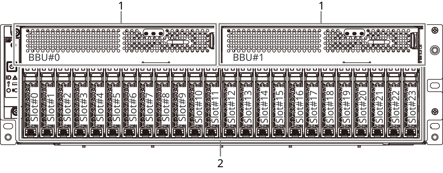
The controller enclosure of the ETERNUS DX600 S6 contains an operation panel, battery units, and NVMe SSDs in the front and controllers (CMs), host interfaces (CAs), drive adapters (DAs), and power supply units in the rear.
Front View

Operation panel
An operation panel has LEDs, a Power switch, and setting change switches.
Front cover
Rear View
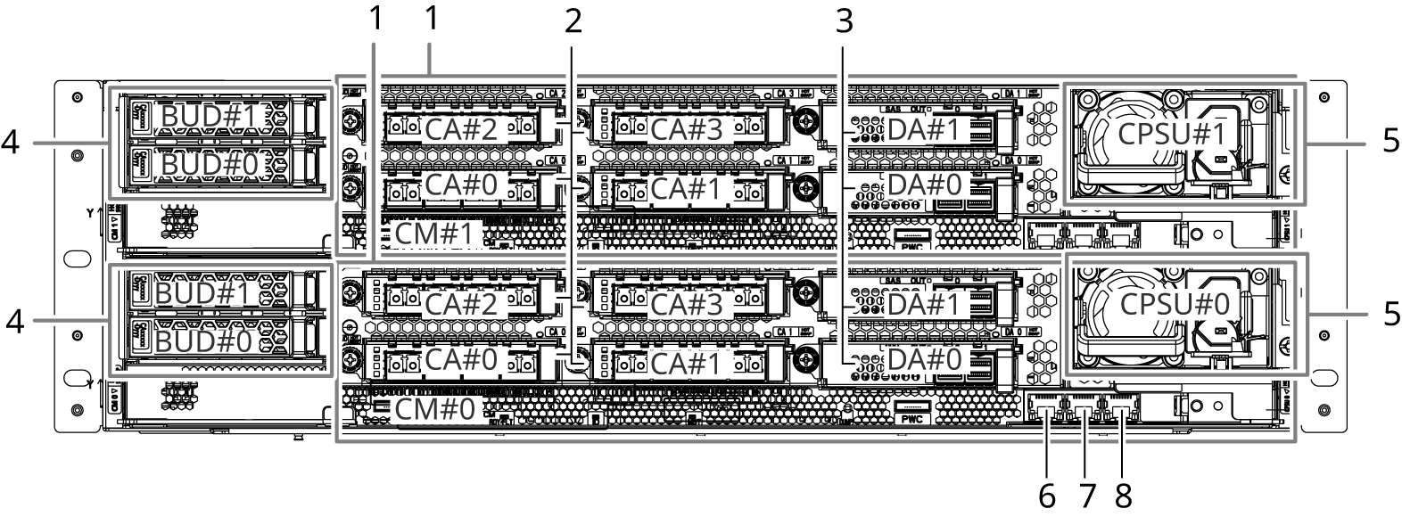
Controller (CM#0, CM#1)
(Refer to Controllers.)
Host interface (CA#0, CA#1, CA#2, CA#3)
(Refer to Host Interfaces.)
Drive adapter (DA#0, DA#1)
(Refer to Drive Adapters.)
BUD (BUD#0, BUD#1)
(Refer to BUD.)
Power supply unit (CPSU#0, CPSU#1)
(Refer to Power Supply Units.)
FST (LAN) port
A port that is dedicated for maintenance engineers. Customers must not use this port.
(Refer to MNT Ports/RMT Ports/FST Ports.)
RMT (LAN) port
(Refer to MNT Ports/RMT Ports/FST Ports.)
MNT (LAN) port
(Refer to MNT Ports/RMT Ports/FST Ports.)