


Add Memory
Overview
This function adds memory while the storage system is operating.
After memory is added to the memory slot of the Controller Module (CM), activate it from Web GUI.
Memory Specifications of Each Model (per CM)
| Model | Memory type | Memory size | Possible number of memory modules installed | Memory expansion unit (per CM) |
|---|---|---|---|---|
| ETERNUS DX100 S5 | 16 GB, 32 GB (*1) | 32 GB, 64 GB | 1 | 1 |
| ETERNUS DX500 S5 | 16 GB, 32 GB, 64 GB | 64 GB, 128 GB, 256 GB | 4 | 4 |
| ETERNUS DX600 S5 | 16 GB, 32 GB, 64 GB | 96 GB, 192 GB, 384 GB | 6 | 6 |
| ETERNUS DX8100 S4 | 16 GB | 48 GB | 3 | 3 |
|
ETERNUS DX900 S5 ETERNUS DX8900 S4 |
16 GB, 32 GB, 64 GB, 128 GB | 96 GB, 192 GB, 384 GB, 768 GB | 6 | 6 |
| ETERNUS AF650 S3 | 64 GB, 128 GB | 384 GB, 768 GB | 6 | 6 |
| *1 | : | The "32 GB" memory type is a "Memory Extension" that is used in the Unified Storage environment. To register a Unified License in a customer environment, "Memory Extension" must be added in advance. |
Perform the start maintenance operation by using the [Start/End Maintenance] function before adding memory. If the operation has not been performed, addition cannot be started.
Be sure to use authorized additional parts. If parts other than the additional parts are used, operation is not guaranteed.
For the ETERNUS DX8900 S4, a license must be registered to use the added memory. Refer to the [Expand System Memory Capacity] function for details.
If the CM to which memory is to be added is a Master CM, the Master CM is switched.
The memory is added to all the enabled CMs installed in the storage system.
This function is not available for the ETERNUS DX60 S5 and the ETERNUS AF150 S3/AF250 S3.
Refer to "Memory Specifications of Each Model (per CM)" to make sure to observe the memory expansion unit when adding memory. If the number of installed memory modules is less than the number of installed memory expansion units, the installed memory modules cannot be used.
Do not add memory when Storage Migration paths are set.
- This function cannot be used under the following conditions:
The general status of the storage system is not normal
The Drive Enclosure (DE) may be blocked
Maintenance for the CM cannot be performed
A recovery operation for the CM is being performed
The Master CM cannot be switched
An error exists in another part
-
If an activation fails midway through the memory adding process for models other than the ETERNUS DX900 S5 and the ETERNUS DX8900 S4, the [Add Memory] function must be executed again.
Perform the following procedure.
Perform a maintenance for the target component that failed to be added.
Restore the memory that failed to be added back to the initial state (by performing a preventive maintenance for the target CM to remove the memory).
Refer to "Hot Preventive Maintenance" for details.
Execute this function again.
Even if an activation fails midway through the memory adding process for the ETERNUS DX900 S5 or the ETERNUS DX8900 S4, the process can be resumed from where it was interrupted by executing this function again after a maintenance for the target component that failed to be added is complete.
For the ETERNUS DX900 S5 or the ETERNUS DX8900 S4, memory is added in descending order from the CM (CE#x CM#y) that is installed in the CE with the largest number. Add the memory in the Master CM last.
The physical capacity of the installed memory in the CM is displayed in the "Memory Size" field on the [Controller Module Detail] screen. Refer to the [Controller Module] function for details.
User Privileges
Availability of Executions in the Default Role
| Default role | Availability of executions |
|---|---|
| Monitor | |
| Admin | |
| StorageAdmin | |
| AccountAdmin | |
| SecurityAdmin | |
| Maintainer |
Refer to "User Roles and Policies" for details on the policies and roles.
Display Contents
The following screens are displayed by the wizard.
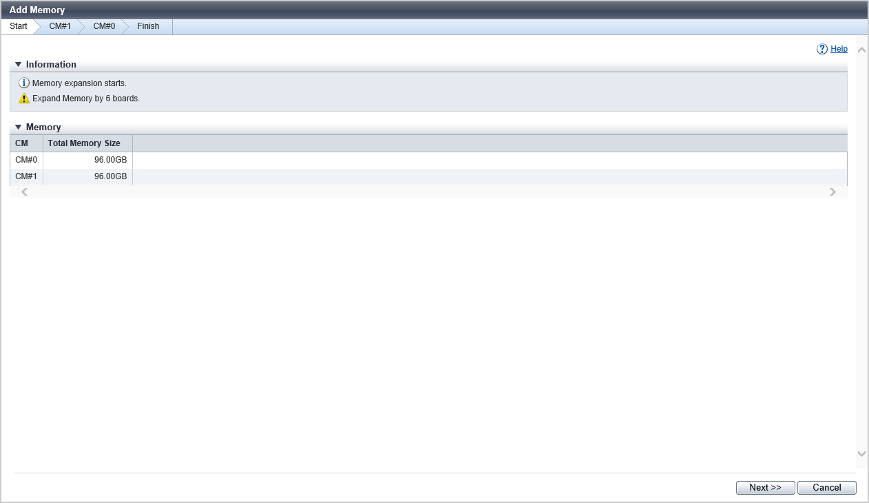
[Start] Screen
A message that indicates the start of memory expansion appears.
In addition, the current memory capacity of the CM is displayed.
Memory
| Item | Description |
|---|---|
CM |
The CM number is displayed. For the ETERNUS DX900 S5 or the ETERNUS DX8900 S4 CE#x CM#y For the other models CM#y x: CE number y: CM number |
Total Memory Size |
The total memory capacity installed on each CM is displayed. |
Activated Memory Size |
The memory capacity that can be used for each CM is displayed. |
[CM#x Start] Screen
The parts information which can be affected by adding memory is displayed.
Expansion Operation
| Item | Description | Setting values | |||
|---|---|---|---|---|---|
Mode |
Select the memory expansion mode.
Note
|
Expansion memory (Default (*1)) Cache memory capacity expansion without memory expansion
|
Memory
| Item | Description |
|---|---|
Target Component |
The CM number to which memory is to be added is displayed. For the ETERNUS DX900 S5 or the ETERNUS DX8900 S4 CE#x CM#y Memory For the other models CM#y Memory x: CE number y: CM number |
Associated Component |
The parts which can be affected by adding memory are displayed. For the ETERNUS DX500 S5/DX600 S5, the ETERNUS DX8100 S4, or the ETERNUS AF650 S3 CM#y CM#y CA#z BUD FAN SFP For the ETERNUS DX900 S5 or the ETERNUS DX8900 S4 CE#x CM#y CE#x CM#y CA#z BUD FAN SFP For the other models CM#y CM#y CA#z BUD SFP x: CE number y: CM number z: CA number |
Total Memory Size |
The total memory capacity installed on the target CM is displayed. |
Activated Memory Size |
The memory capacity that can be used for the target CM is displayed. |
| Item | Description |
|---|---|
Slot |
The slot number in which memory is installed is displayed. Slot#x x: Slot number |
Memory Size |
The installed memory capacity is displayed. |
[Test Connection] Screen
This screen is displayed when the CM to which memory is added is a Master CM.
Follow the displayed procedure to confirm that the new Master CM is connected to a LAN.
Function Button
| Button | Description |
|---|---|
[Test Connection] |
Click this button after confirming that the new Master CM is connected to a LAN. The connection status of the new Master CM and the LAN is checked. |
[Test Connection Result] Screen
This screen is displayed when the CM to which memory is added is a Master CM.
The connection status check result of the new Master CM and the LAN is displayed.
Function Button
| Button | Description |
|---|---|
[Test Connection] |
If connection has failed, reconfirm the new Master CM is connected to a LAN, and click this button. The connection status of the new Master CM and the LAN is checked again. |
[Resume Processing] |
Click this button when connection was successful. Isolation of the CM starts. |
[Isolation Progress] Screen
The progress rate of isolating the CM is displayed.
Status Check
| Item | Description |
|---|---|
CM |
The CM number is displayed. For the ETERNUS DX900 S5 or the ETERNUS DX8900 S4 CE#x CM#y For the other models CM#y x: CE number y: CM number |
Progress |
The progress rate (0 to 100 %) of isolating the CM is displayed. |
Status |
The CM status is displayed. |
[Workflow] Screen
Memory
| Item | Description |
|---|---|
Target Component |
The CM number to which memory is to be added is displayed. For the ETERNUS DX900 S5 or the ETERNUS DX8900 S4 CE#x CM#y Memory For the other models CM#y Memory x: CE number y: CM number |
Total Memory Size |
The total memory capacity installed on the target CM is displayed. |
Activated Memory Size |
The memory capacity that can be used for the target CM is displayed. |
| Item | Description |
|---|---|
Slot |
The slot number in which memory is installed is displayed. Slot#x x: Slot number |
Memory Size |
The installed memory capacity is displayed. |
Workflow Sequence
The procedure to add memory is displayed. Add memory according to the displayed procedure.
[Activation Progress] Screen
The progress rate of the activation process of the CM and the IOM is displayed.
Status Check
| Item | Description |
|---|---|
Parts |
The target CM and the IOM which is connected to the CM are displayed. For the ETERNUS DX900 S5 or the ETERNUS DX8900 S4 CE#x CM#y DE#zz IOM#w For the other models CM#y DE#zz IOM#w x: CE number y: CM number zz: DE number w: IOM number |
Progress |
The progress rate (0 to 100 %) of the activation process of the CM and the IOM is displayed. |
Status |
The status of CM and IOM is displayed. |
[CM#x End] Screen
The CM with the added memory is displayed.
Memory
| Item | Description |
|---|---|
Target Component |
The CM number to which memory has been added is displayed. For the ETERNUS DX900 S5 or the ETERNUS DX8900 S4 CE#x CM#y Memory For the other models CM#y Memory x: CE number y: CM number |
Total Memory Size |
The total memory capacity installed on the target CM is displayed. |
Activated Memory Size |
The memory capacity that can be used for the target CM is displayed. |
| Item | Description |
|---|---|
Slot |
The slot number in which memory is installed is displayed. Slot#x x: Slot number |
Memory Size |
The installed memory capacity is displayed. |
[Finish] Screen
All the CMs to which memory has been added are displayed.
Memory
| Item | Description |
|---|---|
CM |
The CM number is displayed. For the ETERNUS DX900 S5 or the ETERNUS DX8900 S4 CE#x CM#y For the other models CM#y x: CE number y: CM number |
Total Memory Size |
The total memory capacity installed on each CM is displayed. |
Activated Memory Size |
The memory capacity that can be used for each CM is displayed. |
Operating Procedures
Click [Add Memory] in [Action].
→ The [Start] Screen appears.
Click the [Next >>] button.
→ The [CM#x Start] Screen appears.
Check the parts which can be affected by adding memory and click the [Next >>] button.
→ The operations to be started and the displayed screen vary depending on the conditions as follows.
When the CM to which memory is added is a Master CM
→ The Master CM is switched, and the [Test Connection] Screen appears. Proceed to Step 4.
When the CM to which memory is added is a Slave CM
→ The CM isolation process starts, and the [Isolation Progress] Screen appears. When the CM isolation is complete, the [Workflow] Screen appears. Proceed to Step 7.
Note- Note that the [Next >>] button is disabled in any of the following conditions:
"Cache memory capacity expansion without memory expansion" is selected for "Mode"
"Activated Memory Size" has reached the maximum value of the registered memory expansion license
For the ETERNUS DX900 S5 or the ETERNUS DX8900 S4, the [Skip] button is displayed. Clicking this button skips the memory adding process and moves to the [CM#x Start] screen for the next CM.
Follow the displayed procedure to confirm that the new Master CM is connected to a LAN.
After confirming the connection, click the [Test Connection] button.
→ The [Test Connection Result] Screen appears.
Confirm the connection status check result, and click the [Resume Processing] button.
→ CM isolation starts, and the [Isolation Progress] Screen appears. When the CM isolation is complete, the [Workflow] Screen appears.
CautionIf the connection of the new Master CM and the LAN fails, check the connection status again and return to Step 5.
Add memory according to the displayed procedure. When the addition is complete, click the [Next >>] button.
→ The operation to be performed depends on the selected mode.
When "Expansion memory" is selected
→ The CM and IOM activation starts, and the [Activation Progress] Screen appears. When the CM and IOM activation is complete, the [CM#x End] Screen appears.
When "Cache memory capacity expansion without memory expansion" is selected
→ The forced activation of the CM starts. When the force CM activation is complete, the [CM#x End] Screen appears.
Click the [Next >>] button.
→ The [Finish] Screen appears.
CautionIf there is a CM of which memory addition has not been complete, the [CM#x Start] Screen appears. Returns to Step 3.
Click the [Done] button to return to the [Controller Module] screen.