MetroCluster Manuals ( CA08871-401 )
Considerations for sharing private layer 2 networks
MetroCluster IP configurations with supported Cisco switches can share existing networks for ISLs, rather than using dedicated MetroCluster ISLs.
MetroCluster IP switches are dedicated to the MetroCluster configuration and cannot be shared. Therefore, a set of MetroCluster IP switches can only connect one MetroCluster configuration. Only the MetroCluster ISL ports on the MetroCluster IP switches can connect to the shared switches.
| If using a shared network, the customer is responsible for meeting the MetroCluster network requirements in the shared network. |
ISL requirements
You must meet the requirements in:
Required settings on intermediate switches
When sharing ISL traffic in a shared network, the configuration of the intermediate switches provided by the customer must ensure that the MetroCluster traffic (RDMA and storage) meets the required service levels across the entire path between the MetroCluster sites.
The following examples are for Cisco Nexus 3000 switches. Depending on your switch vendor and models, you must ensure that your intermediate switches have an equivalent configuration.
Cisco Nexus switches
The following diagram gives an overview of the required settings for a shared network when the external switches are Cisco switches.
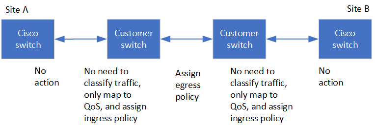
In this example, the following policies and maps are created for MetroCluster traffic:
-
A MetroClusterIP_Ingress policy is applied to ports on the intermediate switch that connect to the MetroCluster IP switches.
The MetroClusterIP_Ingress policy maps the incoming tagged traffic to the appropriate queue on the intermediate switch. Tagging happens on the node-port, not on the ISL. Non-MetroCluster traffic that is using the same ports on the ISL remains in the default queue.
-
A MetroClusterIP_Egress policy is applied to ports on the intermediate switch that connect to ISLs between intermediate switches
You must configure the intermediate switches with matching QoS access-maps, class-maps, and policy-maps along the path between the MetroCluster IP switches. The intermediate switches map RDMA traffic to COS5 and storage traffic to COS4.
The following example shows the configuration for a customer-provided Cisco Nexus 3000 switch. If you have Cisco switches, you can use the example to configure the switch along the path without much difficulty. If you do not have Cisco switches, you must determine and apply the equivalent configuration to your intermediate switches.
The following example shows the class map definitions:
| This example is for configurations using Cisco MetroCluster IP switches. You can follow this example regardless of the switch types of the switches carrying MetroCluster traffic that do not connect to a MetroCluster IP switch. |
class-map type qos match-all rdma
   match cos 5
class-map type qos match-all storage
   match cos 4
The following example shows the policy map definitions:
policy-map type qos MetroClusterIP_Ingress
   class rdma
      set dscp 40
      set cos 5
      set qos-group 5
   class storage
      set dscp 32
      set cos 4
      set qos-group 4
policy-map type queuing MetroClusterIP_Egress
   class type queuing c-out-8q-q7
      priority level 1
   class type queuing c-out-8q-q6
      priority level 2
   class type queuing c-out-8q-q5
      priority level 3
      random-detect threshold burst-optimized ecn
   class type queuing c-out-8q-q4
      priority level 4
      random-detect threshold burst-optimized ecn
   class type queuing c-out-8q-q3
      priority level 5
   class type queuing c-out-8q-q2
      priority level 6
   class type queuing c-out-8q-q1
      priority level 7
   class type queuing c-out-8q-q-default
      bandwidth remaining percent 100
      random-detect threshold burst-optimized ecn
MetroCluster IP Broadcom switches
The following diagram gives an overview of the required settings for a shared network when the external switches are Broadcom IP switches.
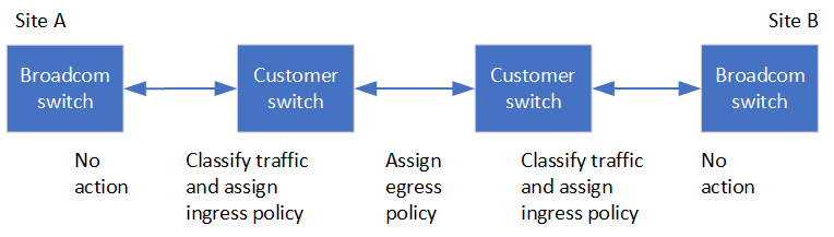
For configurations using MetroCluster IP Broadcom switches, the following additional settings are required:
-
You must configure access-maps and class-maps for the external switches to classify traffic as it enters the network.
This setting is not required in configurations that use MetroCluster IP switches. This example shows how to configure access-maps and class-maps on the first and last switches that connect ISLs between MetroCluster IP Broadcom switches:
ip access-list storage
  10 permit tcp any eq 65200 any
  20 permit tcp any any eq 65200
ip access-list rdma
  10 permit tcp any eq 10006 any
  20 permit tcp any any eq 10006

class-map type qos match-all storage
  match access-group name storage
class-map type qos match-all rdma
  match access-group name rdma
-
You must assign an input policy to the ISL switch port on the first switch.
The following example shows the definition of a class map:
This example is for a configuration that uses Cisco MetroCluster IP switches. Regardless of the switch type, it is available for switches that carry MetroCluster traffic and are not connected to MetroCluster IP switches. class-map type qos match-all rdma match cos 5 class-map type qos match-all storage match cos 4
The following example shows the definition of a policy map:
policy-map type qos MetroClusterIP_Ingress
   class rdma
      set dscp 40
      set cos 5
      set qos-group 5
   class storage
      set dscp 32
      set cos 4
      set qos-group 4
policy-map type queuing MetroClusterIP_Egress
   class type queuing c-out-8q-q7
      priority level 1
   class type queuing c-out-8q-q6
      priority level 2
   class type queuing c-out-8q-q5
      priority level 3
      random-detect threshold burst-optimized ecn
   class type queuing c-out-8q-q4
      priority level 4
      random-detect threshold burst-optimized ecn
   class type queuing c-out-8q-q3
      priority level 5
   class type queuing c-out-8q-q2
      priority level 6
   class type queuing c-out-8q-q1
      priority level 7
   class type queuing c-out-8q-q-default
      bandwidth remaining percent 100
      random-detect threshold burst-optimized ecn
Intermediate customer switches
-
For intermediate customer switches, you must assign the egress policy to the ISL switch ports.
-
For all other interior switches along the path that carry MetroCluster traffic, follow the class map and policy map examples in the section Cisco Nexus 3000 switches.
Examples of MetroCluster network topologies
Some shared ISL network configurations are supported for MetroCluster IP configurations.
Shared network configuration with direct links
In this topology, two distinct sites are connected by direct links. These links can be between Wavelength Division Multiplexing equipment (xWDM) or switches. The capacity of the ISLs is not dedicated to the MetroCluster traffic but is shared with other traffic.
The ISL capacity must meet the minimum requirements. Depending on whether you use xWDM devices or switches a different combination of network configurations might apply.
Shared infrastructure with intermediate networks
In this topology, the MetroCluster IP core switch traffic and the host traffic travel through a network that is not provided by Fujitsu. The network infrastructure and the links (including leased direct links) are outside of the MetroCluster configuration. The network can consist of a series of xWDM and switches but unlike the shared configuration with direct ISLs, the links are not direct between the sites. Depending on the infrastructure between the sites, any combination of network configurations is possible. The intermediate infrastructure is represented as a “cloud” (multiple devices can exist between the sites), but it is still under the control of the customer. Capacity through this intermediate infrastructure is not dedicated to the MetroCluster traffic but is shared with other traffic.
The VLAN and network xWDM or switch configuration must meet the minimum requirements.
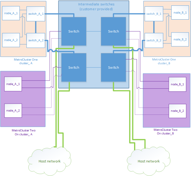
Two MetroCluster configurations sharing an intermediate network
In this topology, two separate MetroCluster configurations are sharing the same intermediate network. In the example, MetroCluster one switch_A_1 and MetroCluster two switch_A_1 both connect to the same intermediate switch.
The example is simplified for illustration purposes only:
Two MetroCluster configurations with one connecting directly to the intermediate network
Two separate MetroCluster configurations share the same intermediate network and one MetroCluster configuration’s nodes is directly connected to the intermediate switch.
MetroCluster One is a MetroCluster configuration using our validated switches, ONTAP 9.7 and a shared topology. MetroCluster Two is a MetroCluster configuration using our compliant switches and ONTAP 9.7.
| The intermediate switches must be compliant with our specifications. |
The example is simplified for illustration purposes only: