MetroCluster Manuals ( CA08871-401 )
Learn about remote storage and MetroCluster IP configurations
You should understand how the controllers access the remote storage and how the MetroCluster IP addresses work.
Access to remote storage in MetroCluster IP configurations
In MetroCluster IP configurations, the only way the local controllers can reach the remote storage pools is via the remote controllers. The IP switches are connected to the Ethernet ports on the controllers; they do not have direct connections to the disk shelves. If the remote controller is down, the local controllers cannot reach their remote storage pools.
MetroCluster IP addresses
You should be aware of how the MetroCluster IP addresses and interfaces are implemented in a MetroCluster IP configuration, as well as the associated requirements.
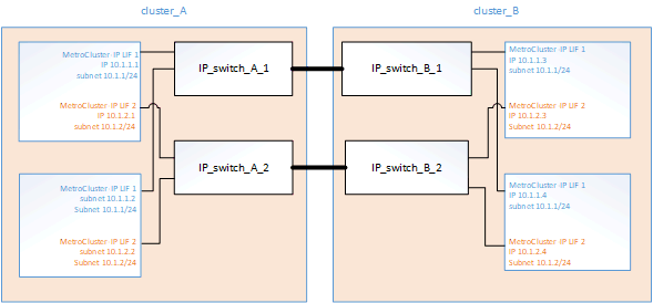
In a MetroCluster IP configuration, replication of storage and nonvolatile cache between the HA pairs and the DR partners is performed over high-bandwidth dedicated links in the MetroCluster IP fabric. iSCSI connections are used for storage replication. The IP switches are also used for all intra-cluster traffic within the local clusters. The MetroCluster traffic is kept separate from the intra-cluster traffic by using separate IP subnets and VLANs. The MetroCluster IP fabric is distinct and different from the cluster peering network.

The MetroCluster IP configuration requires two IP addresses on each node that are reserved for the back-end MetroCluster IP fabric. The reserved IP addresses are assigned to MetroCluster IP logical interfaces (LIFs) during initial configuration, and have the following requirements:
| You must choose the MetroCluster IP addresses carefully because you cannot change them after initial configuration. |
-
They must fall in a unique IP range.
They must not overlap with any IP space in the environment.
-
They must reside in one of two IP subnets that separate them from all other traffic.
For example, the nodes might be configured with the following IP addresses:
Node |
Interface |
IP address |
Subnet |
|---|---|---|---|
node_A_1 |
MetroCluster IP interface 1 |
10.1.1.1 |
10.1.1/24 |
node_A_1 |
MetroCluster IP interface 2 |
10.1.2.1 |
10.1.2/24 |
node_A_2 |
MetroCluster IP interface 1 |
10.1.1.2 |
10.1.1/24 |
node_A_2 |
MetroCluster IP interface 2 |
10.1.2.2 |
10.1.2/24 |
node_B_1 |
MetroCluster IP interface 1 |
10.1.1.3 |
10.1.1/24 |
node_B_1 |
MetroCluster IP interface 2 |
10.1.2.3 |
10.1.2/24 |
node_B_2 |
MetroCluster IP interface 1 |
10.1.1.4 |
10.1.1/24 |
node_B_2 |
MetroCluster IP interface 2 |
10.1.2.4 |
10.1.2/24 |
Characteristics of MetroCluster IP interfaces
The MetroCluster IP interfaces are specific to MetroCluster IP configurations. They have different characteristics from other ONTAP interface types:
-
They are created by the
metrocluster configuration-settings interface createcommand as part the initial MetroCluster configuration.Beginning with ONTAP 9.9.1, if you are using a layer 3 configuration, you must also specify the -gatewayparameter when creating MetroCluster IP interfaces. Refer to Considerations for layer 3 wide-area networks.They are not created or modified by the network interface commands.
-
They do not appear in the output of the
network interface showcommand. -
They do not fail over, but remain associated with the port on which they were created.
-
MetroCluster IP configurations use specific Ethernet ports (depending on the platform) for the MetroCluster IP interfaces.
